Tutorial 4c – Finite cell plate problem
In this tutorial we use Fesslix to analyze the plate problem from the previous tutorial (Tutorial 4b)
using the finite cell approach to solve the problem.
Table of Contents
1 Mechanical model
As in Tutorial 4b, we investigate the problem of the following linear elastic finite element plate with a hole:
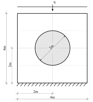
where the distributed load q is 5kN/m. The Young's modulus of the plate is , and
the thickness of the plate is 0.1m.
, and
the thickness of the plate is 0.1m.
Figure 1: Linear elastic finite element plate with a hole investigated in this tutorial.
where the distributed load q is 5kN/m. The Young's modulus of the plate is
, and
the thickness of the plate is 0.1m.
2 Step by Step Instruction
2.1 Define the mesh
Fesslix parameter file
#! ===============================
#! Load the FE module
#! ===============================

loadlib "fem";


#! ===============================
#! Generate the mesh
#! ===============================
# Higher-order shape functions are employed.
# The maximum polynomial order of the shape functions is:
const FEPOX = 8;    # in horizontal (x) direction
const FEPOY = 8;    # in vertical   (y) direction

#! -------------------------------
#! Define the geometry
#! -------------------------------
# The geometry is defined in parametric form.
# Let gx and gy be the global x- and y-coordinates, respectively.
# For a plate in domain [-2,-2] to [2,2], we can write:
var geof = gx^2+gy^2-1;
# where 'geof' is >=0 if we are inside the domain; and <0 if we are outside.
# Note that geof is a simple variable that we will use when setting up the mesh.

#! -------------------------------
#! Define the nodes
#! -------------------------------

node 0 [-2,-2];
node 1 [0, -2] fix wx;
node 2 [2, -2];
node 3 [-2, 0];
node 4 [0,  0];
node 5 [2,  0];
node 6 [-2, 2];
node 7 [0,  2];
node 8 [2,  2];

#! -------------------------------
#! Define the edges
#! -------------------------------

# Control the mesh size
  const ref_x = 1;    # do not sub-divide horizontal edges
  const ref_y = 0.5;  # split-up vertical edge in two

# Edges at bottom of plate:
  edge 1 0 1       # edge 1 from node 0 to node 1
    fix wx 0.0     # fix horizontal displacement along edge
      FEPOX,       # max. polynomial order for horizontal displacement DOFs
    fix wy 0.0     # fix vertical   displacement along edge
      FEPOY        # max. polynomial order for vertical displacement DOFs
    {
      refine=(true,          # refine this mesh
              max=ref_x);    # number of sub-elements: 1/ref_x
    };
  edge 2 1 2 fix wx 0.0 FEPOX, fix wy 0.0 FEPOY { refine=(true,max=ref_x); };

# All other horizontal edges of plate
  edge 3 3 4  free wx FEPOX, free wy FEPOY { refine=(true,max=ref_x); };
  edge 4 4 5  free wx FEPOX, free wy FEPOY { refine=(true,max=ref_x); };
  edge 5 6 7  free wx FEPOX, free wy FEPOY { refine=(true,max=ref_x); };
  edge 6 7 8  free wx FEPOX, free wy FEPOY { refine=(true,max=ref_x); };

# Vertical edges of plate:
  edge 7 0 3  free wx FEPOY, free wy FEPOX { refine=(true,max=ref_y); };
  edge 8 4 1  free wx FEPOY, free wy FEPOX { refine=(true,max=ref_y); };
  edge 9 2 5  free wx FEPOY, free wy FEPOX { refine=(true,max=ref_y); };
  edge 10 6 3 free wx FEPOY, free wy FEPOX { refine=(true,max=ref_y); };
  edge 11 4 7 free wx FEPOY, free wy FEPOX { refine=(true,max=ref_y); };
  edge 12 8 5 free wx FEPOY, free wy FEPOX { refine=(true,max=ref_y); };

#! -------------------------------
#! Define the faces
#! -------------------------------

face 1 1 8 3 7       # face 1 as the area inside edges 1, 8, 3, 7.
  free wx            # degrees of horizontal displacement are NOT fixed
    FEPOX FEPOX        # max. polynomial order of horizontal-DOF-shape functions in
                       # x- and y-direction, respectively.
    true,              # true: use tensor ansatz space; false: use truncated ansatz space
  free wy            # degrees of vertical displacement are NOT fixed
    FEPOY FEPOY        # max. polynomial order of vertical-DOF-shape functions in
                       # x- and y-direction, respectively.
    true               # true: use tensor ansatz space; false: use truncated ans
  {
    condstf = true;  # The internal DOFs of this face are condensed;
                     # i.e., they do not appear globally.
    geo=geof;        # describes geometry within element; negative values indicate 'no geometry'.
    refine_max = 7;  # max. tree-depth to integrate over the boundary of the geometry
  };

face 2 8 2 9 4   free wx FEPOY FEPOY true, free wy FEPOX FEPOX true
  { condstf=true; geo=geof; refine_max=7; };
face 3 11 3 10 5 free wx FEPOY FEPOY true, free wy FEPOX FEPOX true
  { condstf=true; geo=geof; refine_max=7; };
face 4 4 12 6 11 free wx FEPOX FEPOX true, free wy FEPOY FEPOY true
  { condstf=true; geo=geof; refine_max=7; };
2.2 Define the finite elements
Fesslix parameter file
#! ===============================
#! Define the finite elements
#! ===============================

# Material that has Young's modulus 21e4kN/m^2 and Poisson's ratio 0.28
  isomat 0 E 21e4 nu 0.28;

# Plane stress FE-elements
  elplanestr 1 1 {          # element 1 in face 1
      material    = 0;        # the material-number to assign to the element
      t           = 0.1;      # plate thickness [m]
      planestress = true;     # true: plane stress; false: plaine strain
    };
elplanestr 2 2 { t=0.1; };
elplanestr 3 3 { t=0.1; };
elplanestr 4 4 { t=0.1; };
2.3 Define the loads
Fesslix parameter file
#! ===============================
#! Define the loads
#! ===============================
# Apply uniformly distributed load of 5kN/m on top of plate:
  eload 5 local wy pos=[-1,1] load=5;
  eload 6 local wy pos=[-1,1] load=5;
2.4 Solve the system
Fesslix parameter file
#! ===============================
#! Solve the system
#! ===============================

fem assdof;          # assemble degrees of freedom
fem assstf;          # assemble stiffness matrix
fem assforces;       # assemble forces
fem solve {          # solve the system
  printsol=false;      # setting this to true will output the entire solution vector
  pcn=4;               # employ a direct solver
};
2.5 Post-processing
Fesslix parameter file
#! ===============================
#! Post-processing
#! ===============================

#! -------------------------------
#! Displacement at upper left and right corner of plate
#! -------------------------------

# Output the vertical (wy) and horizontal (wx) displacement
# at the left (node 6) and right (node 8) upper corner of the plate:
  funplot nodeu([6,wy]), nodeu([8,wy]), nodeu([6,wx]), nodeu([8,wx]);

#! -------------------------------
#! Vertical displacement at certain points
#! -------------------------------

# Vertical displacement at [-1,2]
  funplot elinfo(
          3,       # id of finite element
          wy,      # retrieve vertical displacement
          -1,      # local x-coordinate (value in [-1,1])
          0        # local y-coordinate (value in [-1,1])
        );
  funplot elinfo(3,wy,0,0);    # Vertical displacement at [-1,1]
  funplot elinfo(3,wy,1,0), elinfo(1,wy,0,1);  # Vertical displacement at [-1,0]
  funplot elinfo(1,wy,0,0);    # Vertical displacement at [-1,-1]
  funplot elinfo(1,wy,0,-1);   # Vertical displacement at [-1,-1]
This displacement in the upper corners should be 1.16mm in vertical direction and 0.24mm in horizontal direction.
3 The complete input files of this tutorial
